Process Overview
Context
To prepare for this project, we spent a semester learning about image processing, actuator control, and hardware design in an Advanced Robotics course taught by Chris Rogers at Tufts University. We carried out several mini projects throughout the semester, from which experiences were accumulated before finally embarking upon creating the Grip N’ Dip.
Ideation
The problem statement posed to the class was to design and build a robot that would take an image (ideally a portrait picture of somebody) and then draw that image in any manner of our choosing (as long as it was recognisable). We discussed several different solution approaches and decided on a computer numerical control (CNC) approach. However, instead of using the conventional belt-gear-pulley system used in CNC machines, we would make a system of racks that our gears would run along in both the X and Y directions.
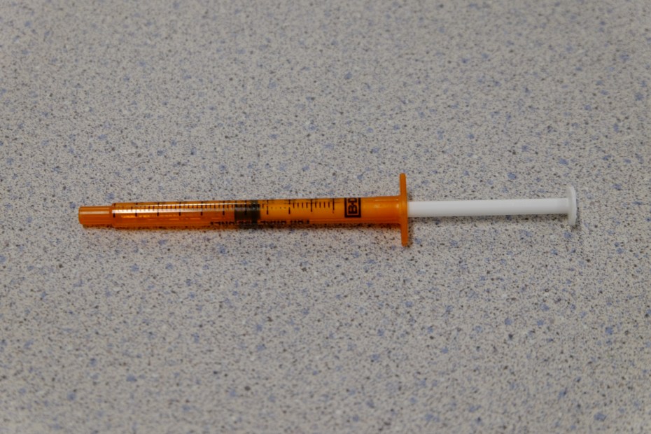
Having decided on that general structure, we then began to ideate ways of implementing the painting mechanism. Our initial idea was to use paint-loaded syringes that would be depressed a certain amount to output a controlled drop of paint. Several syringes would be loaded in a revolving cartridge that would cycle through the syringes / colors. However, after further investigation and a sketchy trip to CVS to acquire syringes, we decided that this was not a feasible method.
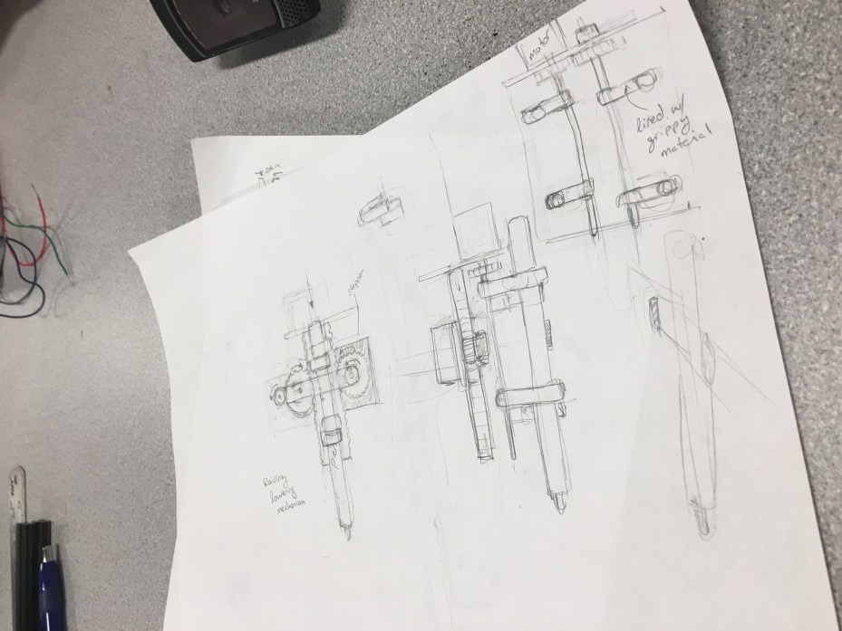
Instead we chose to implement a pen gripper that would travel to a given position and grab a paint pen off a rack. After using the pen, it would simply deposit it back to where it grabbed it from and grab the next pen.
Speccing Hardware
Having chosen a design, we spec’d out and ordered the hardware that we would need to make it possible: stepper motors, motor drivers, frame material, bearings, shafts, and paint markers. A more detailed list of parts ordered can be found here. Any parts that we could not find online, we modeled in SolidWorks for fabrication.
Fabrication
SolidWorks parts that were 3D printed include: shaft mounts, shaft couplers, and pen grippers.
SolidWorks parts that were laser-cut include: motor mounts, gears, and gear racks. The frame was built from 80/20 T-slotted aluminum shafts cut with a vertical band saw.
All parts can be found here.
Software
While all the mechanical pieces were being built, the brain of our robot was being written in LabVIEW. We did a functional decomposition of how our system would work and thus were able to break down the problem into sub VI’s.
The main functions of the code include:
- Processing an image into four colors
- Condensing pixels to a smaller array of pixels
- Converting pixels into XY coordinates
- Moving the motors to a given XY coordinate
- Gripping and releasing the paint pen
- Moving the pen up and down
Building the Grip N’ Dip
Once all hardware parts had arrived and been fabricated, and the heart of the software was complete, we assembled the robot and were able to test our code on it. Finally being able to test our code on our hardware brought to light all the kinks with both the assembly and the code and so began the continuous process of troubleshooting and fine tuning.
The Code
The user uploads an image and selects four colors, and the program condenses the image into these four colors. The program condenses this image into a smaller image of limited pixels, and finds the x and y coordinates of the pixel locations for each of the four colors. These coordinates are sent to another program that facilitates running the motors to paint the portrait. Notice that the Grip N’ Dip prints the portrait upside down. The following image is a snippet of the code that runs the motors. Below that are images of the image processing evolution. The complete code can be found here.


